Causes and effects of rubber degradation
What is rubber degradation?
Most elastomers undergo degradation over time, meaning that all rubber products are subject to degradation throughout their entire product life cycles. Degradation is the reduction in the physical properties such as strength, caused by changes in its chemical composition. In practical terms, if a rubber component starts degrading, it will underperform.
What are the prevalent causes of rubber degradation?
Exposure to heat, chemicals & light
In most cases, deterioration of rubber is caused by exposure to heat (thremo-oxidation), chemicals, light (photo-oxidation), air (ozone cracking) and water (water treeing).
Mechanical & electrical stress
However, ionizing radiation, chemical breakdown, mechanical stress and electric fields are also quite common and create serious physical changes, altering the composition and mechanical properties of rubber products.
Oxidative and thermal aging
Oxidative and thermal ageing of rubber are accelerated by stress and reactive gases, like ozone, resulting in cracking, charring and colour fading. However, the addition of antioxidants, UV stabilisers and antiozonates can slow or prevent these types of issues.
Oxidative rubber degradation can cause hardening or softening, depending on the structure of the elastomer. Hardening is more common because free radicals produced due to heat, oxygen and light combine to form new crosslinks, which reduces the flexibility of the rubber.
From a molecular perspective, these chemical processes are known as “chain hardening” and “chain scission” respectively. The chemical makeup of the polymer will determine which type of deterioration will ultimately occur.
In the following, we’re presenting 6 case studies to show how aging may affect the performance of the rubber component, how they fail and how failure can be avoided.
For more first-hand case studies, visit our case study page.
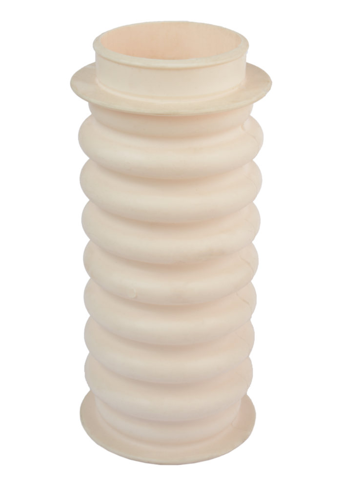
Example for a convoluted below
1. Thermo-oxidation of convoluted bellows
Scenario
A hospital where the central system was constructed with a metal pipe of 100 mm diameter designed to operate at pressures up to 0.6 MPa at water temperatures up to 85 ° ordered 60 fabric reinforced expansion joints.
What are expansion joints/convoluted bellows used for in this case?
The pipe system expands axially that must be accommodated. It is the rubber expansion joints in the form of convoluted bellows that can take the axial expansion and contraction of pipe systems.
The issue
Within 2 years of installation, 20 joints had failed by complete rupture or leaking. These were first noticed soon after the heating system was switched on at the end of the summer.
The rubber was identified using infrared spectroscopy as a blend of natural rubber and polychloroprene. The rubber at the bore of the failed bellows was friable to such an extent that parts had been eroded by the action of pumped water. The inside surfaces were coated in a yellow deposit. On analysis this was found to be a mixture of silicon, zinc, and copper oxides. The local water supply was found to contain high levels of these oxides.
A blend of natural rubber and polychloroprene should be able to provide long service in water at 85 °C without unacceptable thermo-oxidation or hydrolysis. It is known that for many rubbers and plastics (e.g. polyolefins and nylons), certain metal ions accelerate thermo-oxidation by catalysing the reaction.
At 85 °C it is estimated that the high level of ionic copper would reduce durability of the rubber blend by a factor of about 10.
The leaking was evident on restarting the system because under this condition, thermal expansion of the piping was at a minimum and bellows expansion was at a maximum (crack opening).
Solution
The bellows were replaced using a compound with superior resistance to catalysed thermo-oxidative degradation.
Key takeaways
- The durability of rubber components at elevated temperatures is seriously impaired by contact with transition metals in solution.
- Metal ions may be naturally present (as in this case) or they may arise from other sources. A common source is chemical attack of metallic components (e.g. zinc and brass) by the contained/immersion fluid. Thus for example, chlorine water will attack a brass coupling, generate copper chloride in solution, and the ionic copper will catalyse thermo-oxidation of the polymer.
- The bellows had been purchased through an intermediary and selected by them simply on the basis of cost and resistance to water at 85 °C. For rubber components with a critical structural function, direct contact between the supplier and the end customer is strongly recommended.
2. Thermal aging of flexible hoses
Scenario
What are flexible hoses used for?
Flexible hoses are used in a wide range of sizes to convey liquids under pressure. The usual construction is essentially a composite of rubber layers reinforced with steel wire in various configurations. The configuration and complexity of the reinforcement depends on the size of hose and the operating pressure.
Selecting the flexible hose for this application
The rubber compound is selected according to the liquid to be carried and the environmental conditions. One particular design of hose was used to convey water which in one application involved pressures of 0.7–0.8 MPa and temperatures in the range of 20–80 °C.
The issue
Failure occurred by rupture of a hose, raising concern that this was not an isolated problem and the other hoses in service could be at risk.
The hose was relatively small bore and had a simple construction. By sectioning the hose into two halves by means of a band saw it was found that there was a single extruded tube with no inner reinforcement.
The rubber tube was covered with a wire braided layer with a single spiral reinforcement on the outside. After removal of the spiral reinforcement the braiding was exposed and it could be seen that the braiding was ‘shiny’ over much of the length, but there were signs of corrosion near one end fitting. The leakage point through the braiding could be readily seen.
Examination of the inside surface of the hose revealed a split in the rubber beneath the failure point, which was clearly the direct cause of leakage.
The most important observation was that the rubber compound had become embrittled. Bending the cut hose quickly caused cracks to appear on the inner surface and these readily propagated.
This analysis showed that the polymer base was a blend of nitrile and styrene-butadiene rubbers, in a ratio of between 80/20 and 60/40.
Embrittlement due to exposure to heat
The embrittlement of the rubber is a very strong indication that it had been degraded through heat ageing. The ageing results in loss of elongation at break. Splitting of the hose then becomes likely where the inner surface is under tension, such as at a bend, because the strain exceeds the very much reduced ultimate elongation of the rubber. If, as suspected, contamination was present then this would further decrease the strength of the hose.
Lower service temperature due to added SBR
Nitrile rubber is regarded as having a maximum continuous service temperature of the order of 100–120 °C.
However, blending the nitrile with SBR will lower the maximum service temperature, the magnitude of the drop depending on the SBR content.
For the blend identified the maximum allowable service temperature would probably be in the 70–80 °C range.
Conclusion
The conclusion was that the rubber compound used could not withstand long-term service at the maximum temperature of 80 °C and suffered considerable degradation through heat ageing. The consequence of ageing was reduced tensile properties and splitting of the hose.
Key takeaways
- For long-term use a rubber with an adequate continuous service temperature for the conditions expected must be chosen. The material here would have probably been satisfactory at a slightly lower temperature.
- The problem suffered would not become apparent until after a considerable time of service and has implications for all other hoses of the same construction in similar applications.
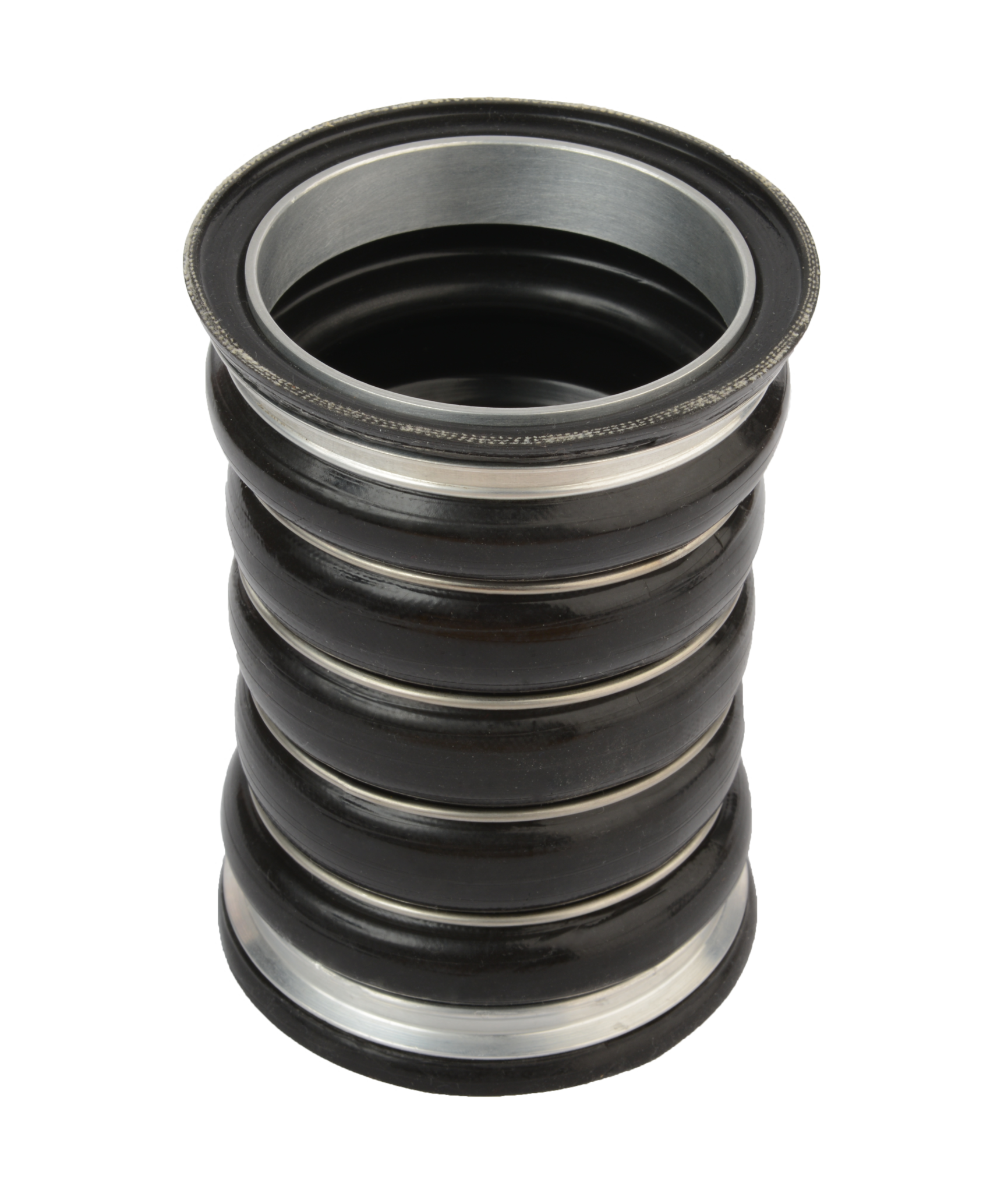
Rubber expansion bellows are used to accommodate expansion and contraction
3. Thermo-oxidation of rubber expansion bellows
Scenario
An industrial heating system using 80 mm diameter steel pipe connected by rubber expansion bellows failed after 18 months in service. The system carried water at 120 °C at pressures of 0.5 MPa. The product had a long successful record in similar applications and under similar service conditions.
The issue
The rubber was confirmed by analysis to be sulphur cured EPDM containing carbon black, naphthenic process oil and inorganic fillers.
The process oil content in unused bellows was found to be 22%, compared with 11% and 9% in rubber removed from the inner and outer layers of the failed bellows.
The respective sulphur contents were 2.5%, 5.8%, and 6.1%. The respective elongations at break were 600%, 450%, and 90%.
The loss of process oil by evaporation is not unexpected at these high operating temperatures. This would contribute to the loss of elongation at break, but clearly it is not a major contribution. The inner and outer layers of the failed bellows have similar oil content but it is only the outer layer that has suffered a severe deterioration in structural properties. This is consistent with thermo-oxidative degradation. Although the outer layer is cooler than the inner layer, it degrades more rapidly because of contact with air.
Excessive sulphur content
The maximum continuous use temperature recommended for sulphur cured EPDM is 120 °C. However this applies to a properly formulated and processed compound. In this case the sulphur content in the failed component is excessive. Excess sulphur acts as a ‘pro-oxidant’ to accelerate degradation.
Conclusion
Failure is due to an error in compounding which compromised the product’s resistance to thermal degradation.
Key takeaways
- Thermal degradation can be accelerated by external catalysts or by internal pro-oxidants such as free sulphur.
- When products are expected to operate at or near to known material limits this needs to be recognised and reflected in the rigour of quality control and assurance procedures.
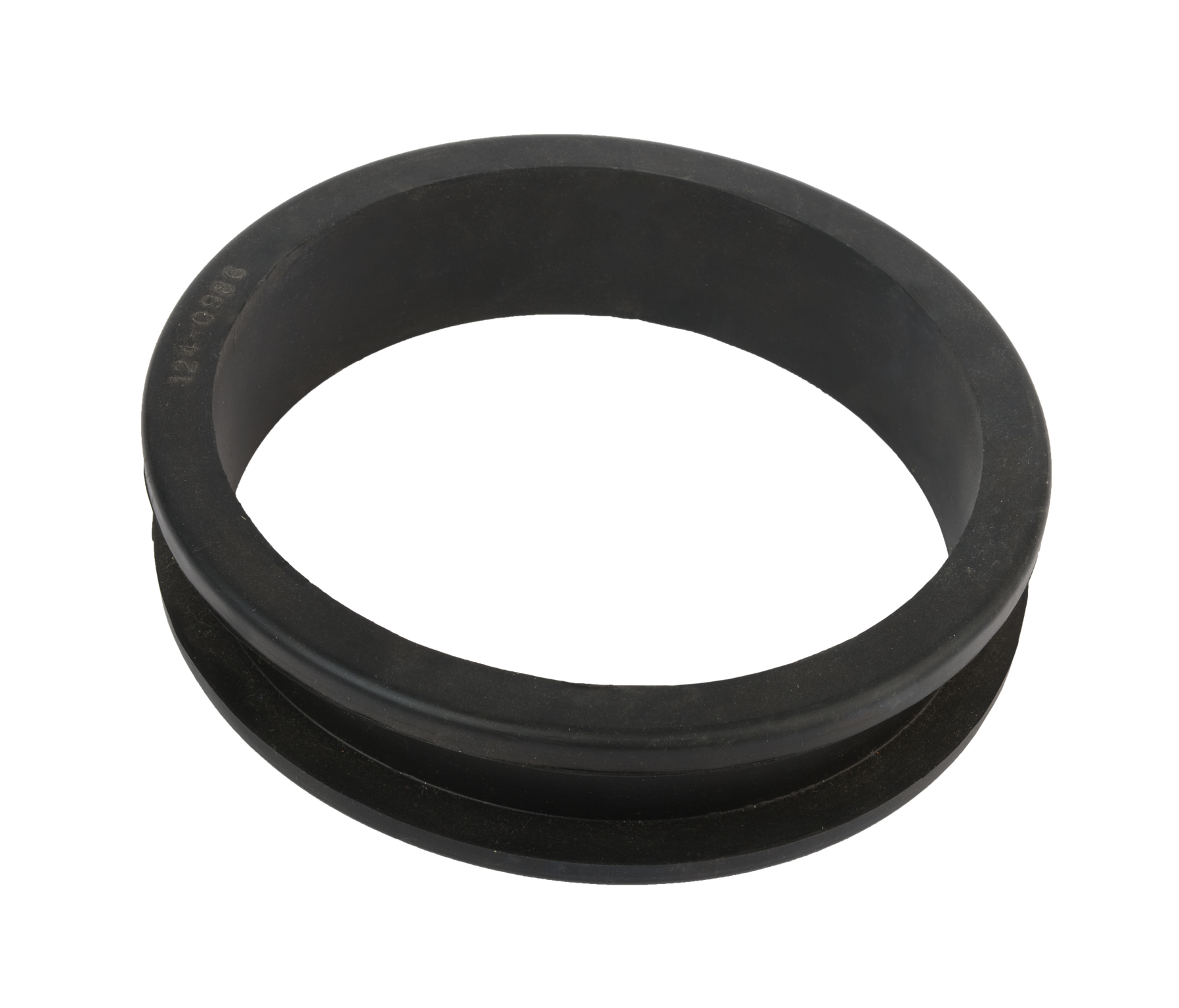
Example for a washer
4. Hydrolytic degradation of TPE washers in hot water
Scenario
A large quantity of TPE washers were supplied and installed from 1990 but failures started to accumulate from 1993. By 1994 when production ceased, failures were numerous and very widespread. The material supplier was asked to investigate the problem. They reported no problem with the material but suggested that considerable compression set on some washers indicated excessive tightening of assemblies. An engineering consultant suggested insufficient tightening. The product supplier could not accept these as credible explanations.
The issue
Failed washers were inspected and a high proportion was found to exhibit radial cracks. The compression set of washers was assessed after three weeks in water at a temperature of 85 °C, the degree of compression being approximately that used in service. Under these conditions, 90% compression set was observed. Other tests under the same exposure conditions showed that the torque to undo assemblies fell to less than 10% of the tightening torque and the washers had severely stiffened.
Thermoplastic elastomers are generally known to suffer from high compression set (high stress relaxation/high creep) compared with thermoset rubbers. For this reason they are rarely chosen for elevated temperature, long-term, pressure sealing applications.
Hydrolytic degradation
It is generally known that polymers with ester groups will offer poor to modest resistance to hydrolytic degradation. Literature states that even with the addition of a hydrolytic stabiliser, the material is ‘generally suitable’ but not ‘very suitable’ for use in water at temperatures above 50 °C. The washer material contained no such stabiliser.
Leaking occurred due to loss of seal pressure and cracking. Both were accelerated by hydrolytic degradation.
Who is responsible for the failure?
In this case the material cause of failure is less revealing than the human cause of failure. The circumstances that triggered the choice of material are of particular interest. The moulder had a successful reputation as a supplier of water tap washers moulded from the specific TPE. This might suggest that he would be aware of some of the limitations of the material. However tap washers operate either at ambient temperatures or short-term at elevated temperatures and they are frequently recompressed. Thus the moulder was unaware of potential problems with compression set or hydrolysis.
The product supplier was also unaware of these limitations. The TPE in question was approved for contact with potable water, and this was interpreted as being ‘approved for use with water’.
Conclusion
As the moulder was confident about the choice of generic material he did not ask the supplier whether this material was the best choice of material but did ask for the best TPE grade. The grade recommended (highest hardness, without hydrolytic stabiliser) suggests that the application was inadequately described or understood. The product was launched without testing.
Solution
The product supplier switched to an EPDM washer. This has proved successful.
Key takeaways
- For material selection, product suppliers should not rely upon the advice of a single processor. They should be particularly wary if the processor advises the use of his favourite material’.
- For functional parts that demand durability, the significance of the product type (e.g. washer, hose, gear wheel, pressure vessel, etc.) should not be overrated or allowed to outweigh the critical factors of time, temperature, stress, and chemical environment. these four factors must be clearly and formally stated if selection advice is sought from material suppliers.
- New products should always be tested. The resources applied to testing should not be based upon a fraction of the product value (which in this case is quite low) but rather upon a fraction of the consequential costs of endemic product failure (which in this case is very high).
Learn about EPDM hoses in the automotive industry here.
5. Shrinkage of ethylene-propylene-diene hose
Scenario
A 6 meter pleasure cruiser burst into flames in a crowded marina. The craft had been moored and unused for 2 years. Fortunately the occupants were able to extinguish the fire before it could spread to adjoining vessels. However the cruiser suffered extensive damage and an insurance claim of around Ł20,000 triggered an investigation into the cause of the conflagration.
The fire started in the engine compartment and it was noted that the rubber hose between the deck filler port and the petrol tank was not securely connected at the tank spigot. However it was not obvious whether this was a cause or effect of the fire.
The issue
The hose material was analysed and identified as an EPDM rubber containing mineral oil as a processing aid. The oil content was assessed to be generally 8% (between the connectors) and 36% in samples taken from above the filler port jubilee clip. The hardness of the rubber was 80 IRHD and 45 IRHD below and above the filler jubilee clip, respectively.
The hose originally supplied was listed as a nitrile. It had been replaced at some unknown point in the cruiser’s history. EPDM is not recommended for contact with petrol or indeed most aliphatic fluids. Petrol swells EPDM to an equilibrium level of ~ 100% with an attendant reduction in hardness.
Mineral oil is not a recommended additive for elastomers in contact with petrol. Mineral oil will be leached out by the petrol, leading to shrinkage of the rubber and an increase in hardness.The mineral oil content in the as-manufactured hose was not known but it could reasonably be assumed to exceed 36%.
On contact with petrol the following sequence of events was initiated:
- Petrol is absorbed and the hose swells by increasing in diameter, wall thickness, and length.
- Petrol extracts most of the processing oil and the swelling effect is moderated by a volume shrinkage of > 28%.
- After several years without use and with the fuel tank emptied (for reasons of safety!) the petrol absorbed by the hose migrated out of the rubber, leading to a net reduction in hose length and wall thickness.
- The reduction in hose wall thickness combined with increased compressive stress relaxation under the jubilee clips whilst swollen reduced the clip retaining force.
- The reduction in hose length generated an axial pull out force that led to the partial disconnection at the fuel tank spigot.
- On refuelling, petrol leaked into the engine compartment.
- Ignition!
Key takeways
- The fact that rubber hoses look alike and are of conveniently similar cross section does not justify the assumption of equivalence.
- Replacement hoses should at best be genuine spare parts or at worst they should be parts that are rated for similar duties.
- As the craft had several previous owners and had been maintained by several boat yards, it was impossible to trace the responsible party.
- The insurance claim was fully settled.
6. Valve sleeves
Scenario
Nitrile rubber sleeves of valves used in the conveyance of mains gas at a pressure of 5MPa had been operated successfully in many installations. However, in one particular application premature failures occurred frequently. This involved only one size of valve and the pressures were not abnormal, although the temperature was 38 °C as opposed to the more usual 10-20 °C. It was expected that valves in these applications would suffer ‘explosive decompression’ due to the expansion of absorbed gas on depressurisation.
However, the failures in this case occurred at operating pressure, and took the form of splits on the outer side of the sleeve and what appeared to be foaming at discrete spots around the inside of the sleeve.
The damage on both surfaces was located on a narrow circumferential band, with splitting on the outside surface facing foaming on the inside surface.
The issue
Details of the formulation used were available, which showed that the material had not been optimised for fatigue resistance, and included an oil-based softener/extender which may not have been fully compatible.
The chemical analysis showed that the material from the foamed region was a badly dispersed material of the same composition as the bulk, and did not contain agglomerates of filler or foreign material.
Tensile strength and elongation were very variable, with strong indication of local flaws.
Both deteriorated sharply at the highest temperature. Dispersion was judged to be rather less good than desirable for a dynamic application.
From the examination it was concluded that the splits were fatigue cracks. It was concluded that the foamed areas were due to expansion of absorbed gas. The circumferential band of damage coincided with the region of highest gas velocity. Gas pressure distributions here would shift and vary significantly with time. The fluctuating stresses due to the expansion of absorbed gases initiated fatigue cracks within the sleeve wall, which propagated in directions dictated by the very complicated strain distribution in the sleeves. This problem was related primarily to the imperfect formulation and the level of dispersion, probably coupled with the quality of moulding for the particular size of sleeve, and the particular operating conditions.
Conclusion
It was not possible to be precise about the main cause of the foaming type of flaw, but it could be deduced that they started from particularly weak areas which were situated in the region of greatest localised dynamic strains. The weak areas could result from a combination of the formulation, dispersion, mould filling and degree of cure defects that preferentially absorb gas. The moulding of this particular size of sleeve and the particular operating conditions resulting in more severe local temperature rise could account for failures in the particular installation.
Key takeaways
- If failures had been more widespread in different installations they would have been simply attributed to the formulation, mixing and moulding being inadequate for the combination of dynamic strain, local temperatures and gas absorption encountered in the application. In fact, failures only occurred in one installation where the conditions were apparently only marginally more severe. It would appear that even a modest change in operating conditions resulted in sufficient increase in local conditions of temperature, dynamic strain and gas absorption to expose the inadequacies of the material.
- The material formulation should have been optimised for fatigue performance by optimising the dispersion of solid additives.
